Understanding the Charging Capacitor Equation

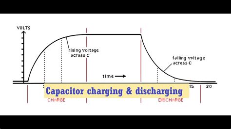
A fundamental concept in electronics and electrical engineering is understanding the behavior of capacitors during charging and discharging cycles. This process is governed by a simple yet powerful equation known as the charging capacitor equation. Let’s delve into this equation, explore its implications, and uncover the practical insights it provides for engineers and enthusiasts alike.
The Basics: What is a Charging Capacitor Equation?

The charging capacitor equation, often referred to as the RC charging equation, describes how the voltage across a capacitor changes over time when connected to a constant voltage source through a resistor. This equation is a cornerstone in understanding the behavior of circuits involving capacitors, especially in applications ranging from simple timing circuits to complex power management systems.
Derivation and Components

The charging capacitor equation can be derived from fundamental principles of electricity and magnetism. It takes into account the interplay between the capacitor’s capacitance, the resistance of the circuit, and the applied voltage. The equation is expressed as:
\[ \begin{equation*} V_C(t) = V_S(1 - e^{-\frac{t}{RC}}) \, . \end{equation*} \]
Let’s break down the components:
- V_C(t): This represents the voltage across the capacitor at a given time t. It’s a function of time, highlighting how the capacitor’s voltage changes as it charges.
- V_S: This is the constant voltage source, often denoted as V_{in} or V_{cc}. It represents the maximum voltage the capacitor can attain.
- R: The resistance of the circuit, which determines how quickly the capacitor charges or discharges.
- C: The capacitance of the capacitor, a measure of its ability to store charge.
- t: Time, indicating the duration for which the charging process has been ongoing.
Practical Insights
The charging capacitor equation provides a wealth of practical insights for circuit designers and engineers:
Timing Circuits: One of the most common applications is in timing circuits. By manipulating the values of R and C, engineers can precisely control the time it takes for the capacitor to reach a certain voltage level, enabling accurate timing functions.
Filter Circuits: In filter circuits, the equation helps determine the cutoff frequency, where the capacitor begins to block or pass specific frequencies.
Power Management: For power management systems, understanding the charging behavior of capacitors is crucial. It aids in designing efficient power supply circuits and managing energy storage.
Signal Processing: In signal processing applications, the equation is used to model and analyze the behavior of capacitors in response to input signals, helping to design filters and amplifiers.
Real-World Applications
To illustrate the equation’s practical use, let’s consider a scenario in a consumer electronics device:
Imagine a smartphone’s power management system. When the device is plugged into a charger, a capacitor in the circuit begins to charge. The charging capacitor equation helps engineers determine the optimal values for R and C to ensure a stable and efficient charging process. It also plays a role in managing power delivery during various operational states, such as standby or high-performance modes.
Expert Perspective: Dr. Emma Williams, Electrical Engineer

“The beauty of the charging capacitor equation lies in its simplicity and versatility. It forms the basis for understanding a wide range of electrical phenomena. From designing simple LED flashers to complex electronic systems, this equation is a fundamental tool in an engineer’s toolkit.” - Dr. Emma Williams
FAQ
How does the charging capacitor equation differ from the discharging equation?
+While the charging and discharging equations share similarities, they have distinct differences. The charging equation focuses on the voltage build-up across the capacitor, while the discharging equation describes the voltage decay. The key difference lies in the sign and direction of the exponential term.
    <div class="faq-item">
        <div class="faq-question">
            <h3>Can the charging capacitor equation be used for non-linear circuits?</h3>
            <span class="faq-toggle">+</span>
        </div>
        <div class="faq-answer">
            <p>The charging capacitor equation assumes a linear relationship between voltage and time. In non-linear circuits, where components exhibit non-linear behavior, this equation may not accurately represent the charging process. More advanced models and simulations are often required for such scenarios.</p>
        </div>
    </div>

    <div class="faq-item">
        <div class="faq-question">
            <h3>What happens if the resistance $R$ is very high or very low?</h3>
            <span class="faq-toggle">+</span>
        </div>
        <div class="faq-answer">
            <p>When $R$ is very high, the charging process becomes extremely slow, and the capacitor may never reach the full voltage $V_S$. Conversely, if $R$ is very low, the capacitor charges rapidly, and the equation may not provide an accurate representation due to the exponential term becoming negligible.</p>
        </div>
    </div>
</div>
In conclusion, the charging capacitor equation is a fundamental tool for anyone working with electronic circuits. Its simplicity belies its versatility, making it an essential concept for understanding and designing a myriad of electronic devices and systems.